Language:
 ∷
∷

∷
 ∷
∷

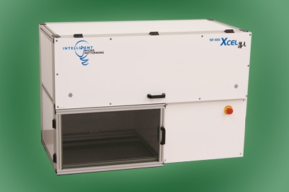
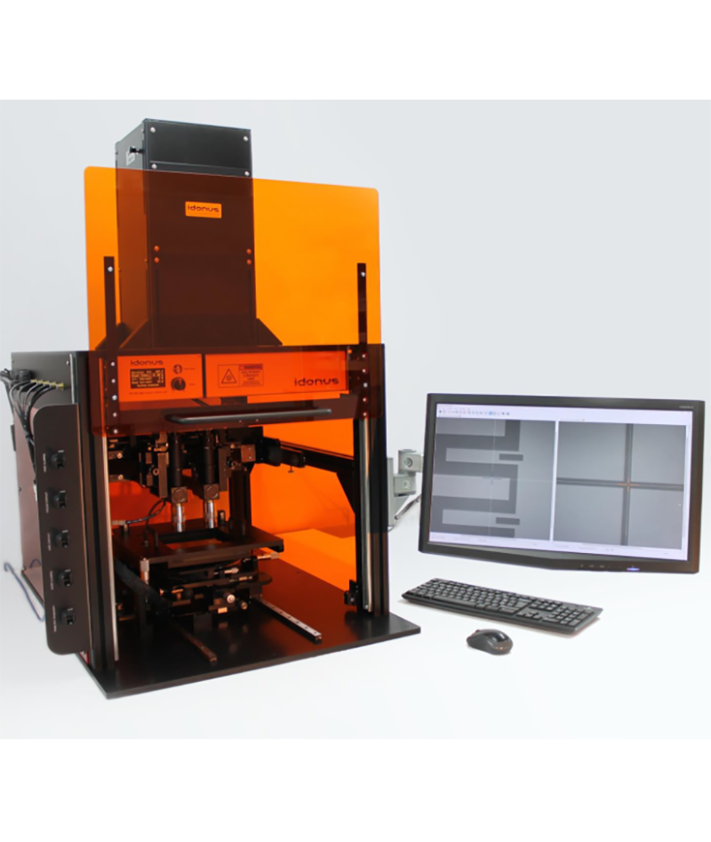
The LaserWriter is a system for direct CAD-to-substrate precision patterning. It can be used both as a general-purpose patterning tool and as a specialized system for fulfilling specific research or production needs.
The LaserWriter is a system for direct CAD-to-substrate precision patterning. It can be used both as a general-purpose patterning tool and as a specialized system for fulfilling specific research or production needs. The system is completely assembled in clean room and is composed of the following parts:
Write unit
Control unit
PhotonSteer® software package
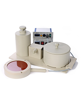
Environmental control unit (optional)
Applications include direct substrate patterning and mask fabrication for microelectronics, micro-optics, microwave circuits, terahertz technology, micromechanics, microfluidics, graphene technology, etc.
Patterning can be made on any resist-coated substrate, like semiconductor wafers or chips, glass, Sapphire, polymers, etc.
The configuration described here follows WHU requirements.
The system is CE certified.
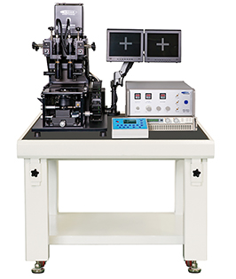
Write unit
- Solid state GaN laser for general lithography on any standard broadband resist film (AZ, S) and thin SU8 (< 5 μm), with the following specifications:
Laser type: semiconductor (GaN)
Wavelength: 405nm
Operating Mode: continuous (CW) and pulsed.
Output power (operator adjustable), to be defined on order:
50-100 mW, for standard 0.2-10 μm thick resist
50-250 mW, for thick resist
50-400 mW, for thick resist.
Guaranteed lifetime: 20,000 hours.
- Optional aditional 375 nm GaN laser specific for SU8 or other UV-sensitive resist thicker than 5 μm, with the following specifications:
Laser type: semiconductor (GaN)
Wavelength: 375 nm
Operating Mode: continuous (CW) and pulsed.
Output Power: 60 mW.
Guaranteed lifetime: 20,000 hours..
- Wavelength switching with a mouse click.
- Write field (mm): 160x160
- Substrate size (mm): from 5x5 to 200 mm x 200 mm.
- Substrate thickness: 0 to 10 mm.
- Ultraprecision XY stages, with linear motors and nanopositioning capability, with 10 nm static resolution.
- Multilayer patterning with +/- 0.4 μm overlay alignment accuracy (for an operating environment stabilized within +/- 1°C) and tools for alignment on existing marks.
- Selectable automatic or manual registration for multilayer overlay.
- Ultraprecision Z stage with +/- 2.4 mm range and 0.1 μm accuracy.
- Optical autofocus and surface tracking, allowing automatic focusing and patterning
on uneven or slightly tilted substrates, with automatic compensation (3 degrees maximum tilt)
up to the edge of the substrate, even for small samples (5x5 mm)
on slightly convex or concave surfaces (75 mm min. curvature radius) or surfaces with waviness.
- Grey-level patterning capability, with 256 levels, in both beam-scan and stage-scan modes.
- Positive and negative patterning.
- X or Y or XY mirrored patterning.
- Seven write modes: beam raster scan, stage raster scan, vector, contour, scatter-scan, flash, manual. Any XY stage movement is programmed, with position-synchronized beam on/off.
- Beam scan: this is the standard write mode: the whole pattern is converted into a bitmap image and divided into parallel strips. The laser beam is scanned on the substrate while this moves along each strip (Y direction), orthogonal to the scanning direction (X). The bitmap pattern is obtained by modulating the beam during each scan. After completing one strip, the stages move to the top of the next strip and the process is repeated. All strips are precisely aligned to each other, with no visible stitching error between adjacent strips.
- Stage scan: the beam is kept still, and the raster scan path is obtained by fast moving forth and back the X stage along the whole width of the pattern, while the Y stage moves slowly.
- Vector: this is well suited for patterning long isolated lines or for specific applications (photochemistry, trimming, etc.). The beam is kept still and the xy stage provides for plotting the lines that make up the pattern.
- Contour: the beam is kept still and the xy stage moves for plotting all designed lines and arcs.
- Scatter-scan: this is a proprietary write mode, disclosed to final users only on system installation.
- Flash: this is a proprietary write mode, disclosed to final users only on system installation.
- Manual: this mode allows the user to manually drive the laser beam along the desired pattern, following the process directly on the video window.
- Optical resolution (minimum linewidth), selectable by replacing the final focusing lens:
405 nm laser:
0.5 μm with a feature positioning resolution of 0.1 μm, on > 0.4 μm thick resist
1.6 μm, with a feature positioning resolution of 0.2 μm
4 μm, with a feature positioning resolution of 0.4 μm
8 μm, with a feature positioning resolution of 0.8 μm
Optional 375 nm laser
5 μm, with a feature positioning resolution of 0.5 μm and 40 μm depth of focus
.
All resolutions included. The resolution is changed by replacing the final focusing lens. All focusing lenses are installed in a slider and their manual selection requires only two seconds.
- Optional Automatic Lens Change system (ALC), allowing lens change with just a mouse click. The ALC allows also unattended lens change and automatic realignment on a previous layer, according to a batch program defined by the user.
- Range of surface patterning speed in beam-scan mode (raster scanning) @ 405 nm:
2-8 mm²/min @ 0.5 μm resolution, with feature positioning resolution from 0.1 to 0.4 μm
8-30 mm²/min @ 1.6 μm resolution, with feature positioning resolution from 0.2 to 0.8 μm
30-120 mm²/min @ 4 μm resolution, with feature positioning resolution from 0.4 to 2 μm
120- 450 mm²/min @ 8 μm resolution, with feature positioning resolution from 0.8 to 4 μm
- Linear write speed in stage-scan, vector and contour mode: up to 10 mm/s at all resolutions.
- Write time calculator. The software estimates the total required time before starting a new pattern. While patterning proceeds, the remaining time is calculated and shown.
- Tools for exposure dose calibration.
- Edge roughness in beam-scan and scatter-scan modes as a function of write speed:
0.05 to 0.2 μm @ 2-8 mm²/min @ 0.5 μm resolution
0.1 to 0.4 μm @ 8-30 mm²/min @ 1.6 μm resolution
0.1 to 1 μm @ 30-120 mm²/min @ 4 μm resolution
0.4 to 2 μm @120- 450 mm²/min @ 8 μm resolution
- Linewidth uniformity as a function of resolution
100 nm @ 0.4 and 0.5 μm resolution
200 nm @ 1.6 μm resolution
400 nm @ 4 μm resolution
800 nm @ 8 μm resolution
- Exposure control with step (coarse) and continuous (fine) regulation, with dose indication (mJ/cm2).
- Focus shift control in Z direction, up to ± 100 μm.
- Substrate visual monitoring, by a B&W digital video-camera, including red light substrate illumination, image averaging and frame grabbing. The system is also a precision metrology tool with 0.1 μm resolution. The lens change mechanics allows also a fast selection of the field of view (800, 400, 200, 100 μm), like a traditional microscope. Metrology tools are included.
- Optional additional wide field microscopy (2.5 mm), for fast pattern location when the system is used as a microscope or for the search of alignment marks.
- Substrate viewing while patterning, through the same lens used for laser focusing.
- Video tools for assisting the operator on precision multilayer alignment and substrate positioning.
- Customizable vacuum chuck for the substrate. The chuck can host wafers, chips and masks with thickness in the 0 to 10 mm range. Substrates of any size and shape can be used, from 5x5 mm. The chuck contains also relocatable stops for precisely positioning substrates with standard sizes. Customized stops can be defined on order.
- Optional additional porous ceramic vacuum chuck for thin flexible substrates or for loading more small chips on the chuck..
- Oil-free vacuum pump for the chuck with remote control through software . If a vacuum line is available at the installation site, a vacuum switch with automatic venting and remote control can be ordered in place of the vacuum pump.
- Possibility of full manual control of the system, for surface inspection and measurements.
- Write head on a vibration-damped stainless-steel frame, for placement on the floor.
Approx. weight: 120 kg.
No compressed air required, no cooling air duct, no water.
The maximum operating voltage inside the write unit is 12 V.
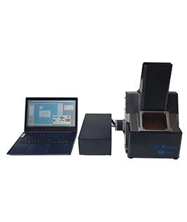
Control unit
All electronics is contained in 19” standard rack units placed below the write head, in a rack cabined on wheels. No additional floor space is required for the control unit. The 19” x 4U units include:
User-interface computer (industrial-level computer, with i7-8th generation CPU and 16 GB memory) running under Windows10- pro, 64 bit.
.Electronic drivers for the write unit.
Optional uninterruptible power supply (UPS), with 30 min. backup time.
Computers and power supplies comply with international safety standards. No high voltage is used throughout the LaserWriter, besides the computer power supplies (115-230 V). A button for emergency full power-off is included, as well as an interlock in the substrate loading door for automatic laser off.
The control unit manages the automatic patterning process, from drawing to exposure, as well as manual operation (when using the system as a precision video-metrology tool). It allows the operator to define and control all patterning parameters.
Contact: Nick.Zhang
Phone: 13916855175
Tel: 021-56035615
Email: info@crosstech.com.cn
Add: Suite902,No.3,Magnolia Green Square,Lane251,SongHuaJiang Road,Shanghai,China,200093